High security fence (chain link ) installation involves following five steps generally:
Secure mesh (chain link) fabrics
Secure posts
Install the gate
Install the barbed wire
Install the barbed tape
METAL POSTS preparing
All Fence Posts conforming to ASTM F1083, zinc-coated or KS D 3507. Group IA, with external coating Type A steel pipe. Group IC steel pipe, zinc-coated with external coating Type A or Type B and Group II , roll-formed steel sections, meeting the strength and coating requirements of ASTM F1043 and ASTM A702. Group III, ASTM F1043 steel H-section may be used for line posts in lieu of line post shapes specified for the other classes.
Line posts and terminal (corner, gate, and pull) posts selected shall be of the same designation throughout the fence.
Gate post for the gate type specified subject to the limitation specified in ASTM F900 and/or ASTM F1184.
Post spacing shall conform to the recommended guidelines as set forth in the CLFMI "Wind Load Guide for the Selection of Line Post Spacing and Size" unless specified to exceed those guidelines.
Fence Accessories
Accessories conforming to ASTM F626. Ferrous accessories shall be zinc or aluminum coated.
Furnish truss rods for each terminal post. Truss rods with turnbuckles or other equivalent provisions for adjustment.
Barbed wire supporting arms of the 45 degree outward angle 3-strand or V 6 strand arm type and of the design required for the post furnished.
Secure arms by top tension wire or top rail and bolting.
Furnish post caps in accordance with manufacturer's standard accessories.
9 gauge steel tie wire for attaching fabric to rails, braces, and posts and match the coating of the fence fabric. Tie wires for attaching fabric to tension wire on high security fences shall be 1.6 mm stainless steel.
Double loop tie wires 165 mm in length.
Miscellaneous hardware coatings shall conform to ASTM A153/A153M unless modified.
BRACES AND RAILS
ASTM F1083, zinc-coated, Group IA, steel pipe, size NPS 1-1/4 or KS D 3507, zinc-coated. Group IC steel pipe, zinc-coated, shall meet the strength and coating requirements of ASTM F1043. Group II, formed steel sections, size 42 mm, conforming to ASTM F1043, may be used as braces and rails if Group II line posts are furnished.
Preparing for Installation
Clear the area on either side of the fence line. Space line posts equidistant at intervals not exceeding 3 m. Terminal (corner, gate, and pull) posts shall be set at abrupt changes in vertical and horizontal alignment. Provide fabric continuous between terminal posts; however, runs between terminal posts shall not exceed 152.4 m.
Clear all post holes of loose material. Spread waste material where directed. Eliminate ground surface irregularities along the fence line to the extent necessary to maintain a 50 mm clearance between the bottom of the fabric and finish grade.
Brace Details for Securing Post:
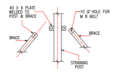
Set posts plumb and in alignment. Where solid rock is encountered with no overburden, set posts to a minimum depth of 457 mm in rock. Where solid rock is covered with an overburden of soil or loose rock, set posts to the minimum depth indicated on the drawing unless a penetration of 457 mm in solid rock is achieved before reaching the indicated depth, in which case terminate depth of penetration. Grout all portions of posts set in rock.
Portions of posts not set in rock shall be set in concrete from the rock to ground level. Posts set in concrete shall be set in holes not less than the diameter shown on the drawings.
Make diameters of holes in solid rock at least 25 mm greater than the largest cross section of the post.
Thoroughly consolidate concrete and grout around each post, free of voids and finished to form a dome.
Allow concrete and grout to cure for 72 hours prior to attachment of any item to the posts.
Group II line posts may be mechanically driven, for temporary fence construction only, if rock is not encountered. Set driven posts to a minimum depth of 914 mm and protect with drive caps when setting.
Test fence post rigidity by applying a 222.4 newtons force on the post, perpendicular to the fabric, at 1.52 m above ground. Post movement measured at the point where the force is applied shall be less than or equal to 19 mm from the relaxed position. Test every tenth post for rigidity. When a post fails this test, make further tests on the next four posts on either side of the failed post. All failed posts shall be removed, replaced, and retested.
SECURING RAILS
Bolt bottom rail to double rail ends and securely fasten double rail ends to the posts. Peen bolts to prevent easy removal. Install bottom rail before chain link fabric. 3/8" diameter eye hook anchored into concrete footing at midpoint.
Chain LInk FENCE FABRIC preParing
ASTM A392, Class 2, zinc-coated steel wire with minimum coating weight of 610 grams of zinc per square meter of coated surface or KS D 7011, SWMGS-7; or, ASTM A491, Type I, aluminum-coated steel wire or KS D 7037, Class SWMA-C. KS D 7037, Class SWMA-C shall meet minimum breaking strengh and adherence of coating on ASTM A491.. Class 2b polyvinyl chloride-coated steel fabric with 92 grams of zinc coating per square meter in accordance with ASTM F668.
Fence fabric of 9 gauge wire woven in 50 mm mesh conforming to ASTM A116.
Fabric shall be twisted and barbed on the top selvage and knuckled on the bottom selvage.
Secure fabric to posts using stretcher bars or ties spaced 375 mm on center, or by integrally weaving to integral fastening loops of end, corner, pull, and gate posts for full length of each post.
Install fabric on opposite side of posts from area being secured.
Chain Link fence burried into Ground Beam, Details
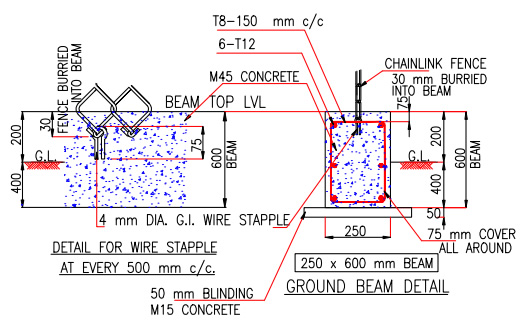
Install chain link fabric on the side of the post. Attach fabric to terminal posts with stretcher bars and tension bands. Space bands at approximately 381 mm intervals. Install fabric and pull taut to provide a smooth and uniform appearance free from sag, without permanently distorting the fabric diamond or reducing the fabric height. Fasten fabric to line posts at approximately 381 mm intervals and fastened to all rails and tension wires at approximately 305 mm intervals.
Cut fabric by untwisting and removing pickets. Accomplish splicing by weaving a single picket into the ends of the rolls to be joined. The bottom of the installed fabric shall be 25 mm plus or minus 13 mm above the ground.
After the fabric installation is complete, exercise the fabric by applying a 222 newtons push-pull force at the center of the fabric between posts; the use of a 133 newtons pull at the center of the panel shall cause fabric deflection of not more than 63.5 mm when pulling fabric from the post side of the fence; every second fence panel shall meet this requirement; resecure and retest all failed panels at the Contractor's expense.
Preparing
Gate Assembly
Gate assembly conforming to ASTM F900 and/or ASTM F1184 of the type and swing.
Gate frames conforming to strength and coating requirements of ASTM F1083 for Group IA, steel pipe, with external coating, nominal pipe size (NPS) 1-1/2 or KS D 3507.
Gate frames conforming to strength and coating requirements of ASTM F1043, for Group IC, steel pipe with external coating, nominal pipe size (NPS) 1-1/2.
Gate fabric: chain link fabric.
Gate Leaves:
For gate leaves, more than 2.44 m wide, provide either intermediate members and diagonal truss rods or tubular members as necessary to provide rigid construction, free from sag or twist.
Gate leaves less than 2.44 m wide shall have truss rods or intermediate braces.
Intermediate braces on all gate frames with an electro-mechanical lock.
Attach fabric to the gate frame by method standard with the manufacturer except that welding will not be permitted.
Gate Hardware and Accessories: Furnish and install latches, hinges, stops, keepers, rollers, and other hardware items as required for the operation of the gate. Arrange latches for padlocking so that the padlock will be accessible from both sides of the gate.
Stops for holding the gates in the open position.
For high security applications, each end member of gate frames shall be extended sufficiently above the top member to carry three strands of barbed wire in horizontal alignment with barbed wire strands on the fence.
Padlocks conforming to ASTM F883, Type PO1 , Option A, B, and G and , Grade 6 . Size 44 mm. Key all padlocks alike.
Electric gate operators for sliding gates as follows: Electrical gate operators shall have a right angle gearhead instantly reversing motor with magnetic drum-type brake, friction disc clutch, reversing starter with thermal overload protection, and a chain-driven geared rotary-type automatic limit switch. Gears shall consist of a hardened steel machine cut worm and mating bronze gear.
All gears and bearings shall operate in a bath of oil. Gate operators with V-belt pulleys are not allowed. Equip gate operators with an emergency release to allow the gate to be operated manually. The emergency release mechanism shall be capable of being locked in the engaged or disengaged position. Provide positive stops on the gate tracks as a backup to the limit switches.
Electro-mechanical locking devices for sliding gates and personnel gates shall be solenoid actuated such that the deadbolt retracts when the solenoid is energized and remains electrically retracted until the gate is closed. Provide continuous duty type solenoid, rated for 120V ac, 60Hz operation. The locking device shall be unlockable by key and keyed on both sides. Status of the electro-mechanical lock shall be monitored by two limit switches (integral to the locking device) wired in series. One switch shall monitor the deadlock lever and the other monitor the locking tongue.
Mount gates to swing.
Install latches, stops, and keepers as required.
Install Sliding or Double Swing gates as recommended by the manufacturer.
Attach padlocks to gates or gate posts with chains. Weld or otherwise secure hinge pins, and hardware assembly to prevent removal.
Submit operating and maintenance instructions, prior to field training.
Operating instructions shall outline the step-by-step procedures required for system startup, operation, and shutdown. Include the manufacturer's name, model number, service manual, parts list, and brief description of all equipment and their basic operating features. Include in the maintenance instructions routine maintenance procedures, possible breakdowns and repairs, and troubleshooting guide. Also include the general gate layout, equipment layout and simplified wiring and control diagrams of the system as installed.
Wire Ties
Wire ties constructed of the same wire material as the fencing fabric.
Barbed Wire
Barbed wire conforming to ASTM A121 zinc-coated, Type Z, Class 3, or aluminum-coated, Type A, with 12.5 gauge wire with 14 gauge, round, 4-point barbs spaced no more than 125 mm apart.
Tension Wire
Class 4 coating, in accordance with ASTM A824 or KS D 7037, SWMA-A or KS D 7011 SWMGS-7.
BARBED TAPE
Barbed tape, double coil or single coil, for fence toppings fabricated from 430 stainless steel or hot dipped galvanized
Stainless steel or galvanised steel strip 0.6 mm thick by 25 mm wide before fabrication.
Each barb shall be a minimum of 30.5 mm in length, in groups of 4, spaced on 102 mm centers.
Non-reinforced barbed tape, single coil, for ground applications shall be fabricated from 301 series stainless steel, with a hardness range of Rockwell (30N) 50-55, in accordance with ASTM A666. The stainless steel strip shall be 0.6 mm thick by 31 mm wide before fabrication. Each barb shall be a minimum of 30.5 mm in length, in groups of 4, spaced on 102 mm centers. Hot dipped galvanized barbed tape is supplied at less cost.
Wire ties are used for attaching the barbed tape to the barbed wire and to the fence
SUPPORTING ARMS
Install barbed wire supporting arms and barbed wire as indicated on the drawings and as recommended by the manufacturer. Anchor supporting arms to the posts in a manner to prevent easy removal with hand tools with 9.5 mm diameter plain pin rivets or, at the Contractor's option, with studs driven by low-velocity explosive-actuated tools for steel, wrought iron, ductile iron, or malleable iron. Studs driven by an explosive-actuated tool shall not be used with gray iron or other material that can be fractured. Use a minimum of two studs per support arm. Pull barbed wire taut and attach to the arms with clips or other means that will prevent easy removal.
Install barbed tape: Stretch out barbed tape to its manufacturer's recommended length, set on top of the barbed wire and "V" shaped support arms, then secure it to the barbed wire. Secure the barbed tape to the barbed wire at the two points and at every spiral turn of both coils.
Install reinforced barbed tape for ground applications in accordance with requirement or the drawings.
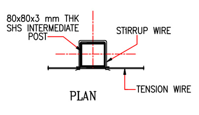
Intermediate post: for installation of barbed tape topping:
Stirrup Wire: For fixing intermediate post: